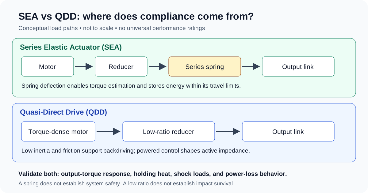
Series Elastic Actuators (SEA) vs Quasi-Direct Drive (QDD) Joint Modules: Force Bandwidth, Energy Recovery, and Humanoid Sourcing Guide
Compare SEA vs QDD robotic joint modules for force bandwidth, energy recovery, holding heat, and OEM sourcing. Use the checklist to prepare your actuator RFQ.
Series Elastic Actuators (SEA) vs Quasi-Direct Drive (QDD) joint modules: shortlist an SEA when intentional spring deflection, torque sensing, and potential elastic energy reuse suit the load cycle. Shortlist a QDD when low reflected inertia, backdrivability, and responsive torque control are priorities. Compare measured output behavior under the same load conditions before choosing either architecture.
Neither topology offers a universal solution. An SEA introduces spring travel and resonance constraints; a QDD's low reduction ratio can increase holding-current demand. A spring does not guarantee safe behavior during a power loss, and a low gear ratio does not guarantee low friction or impact survival.
This engineering and procurement guide gives robot hardware architects and OEM sourcing teams a decision framework for humanoids, quadrupeds, wearable exoskeletons, and collaborative manipulation arms.
Published and reviewed: November 2, 2026. Scope: Global OEM sourcing, English-language engineering guidance. This is a literature-informed comparison with explicitly hypothetical calculations, not a report of factory tests or certified product performance. The schematic illustrates load paths rather than a saleable configuration. Application-specific testing and the destination market's applicable requirements remain necessary.
If you are preparing prototype or pilot orders, evaluate our modular robotic joint actuator portfolio or send your load profiles to our engineering team for an RFQ review.
1. Executive Summary & Sourcing Trade-Off Matrix
The fundamental architectural difference is intentional series elasticity versus a drivetrain designed for low mechanical impedance. An SEA puts a compliant element in the load path and can estimate torque from calibrated spring deflection. A QDD combines a relatively low reduction ratio with a torque-dense motor; low inertia and friction enable passive backdriving, while feedback control adds active impedance behavior. Neither name fixes a universal gear ratio, package size, or bandwidth.
| Architectural Metric | Series Elastic Actuator (SEA) Module | Quasi-Direct Drive (QDD) Module | Sourcing & Procurement Impact |
|---|---|---|---|
| Compliance mechanism | An intentional spring deflects under load, including when unpowered, within its travel limits. | Low mechanical impedance supports backdriving; active stiffness and damping require working controls. | Verify power-loss behavior, brakes, hard stops, and stored energy for both. |
| Transmission ratio | Can use different reducer types and ratios; high reduction is one design option. | Usually uses relatively low reduction; 4:1–10:1 is an illustrative range, not a definition. | Compare motor size, output inertia, speed, and friction together. |
| Torque sensing | Calibrated spring deflection, measured by encoders or another displacement sensor. | Often inferred from motor current, with optional output torque sensing. | Require accuracy, hysteresis, temperature drift, and friction compensation data. |
| Force-control bandwidth | Depends on stiffness, motor dynamics, load condition, sensing, and controller design. | Depends on current-loop dynamics, transmission, sensing, delay, and load. | Compare measured output-torque frequency responses at matched amplitude and boundary conditions. |
| Impact behavior | Spring deflection can reduce transmitted peaks before travel is exhausted. | Low reflected inertia can reduce impact force; gears and bearings still carry loads. | Require application-representative shock tests rather than topology-based assurances. |
| Energy reuse | Stores strain energy that may assist a later phase of motion. | May return negative mechanical work electrically if the drive and DC bus accept it. | Compare battery energy over the same complete task and verify bus protection. |
| Static holding heat | A higher ratio may reduce current, but the spring alone does not remove holding torque. | A low ratio may demand more motor torque; motor sizing and cooling can compensate. | Require continuous holding tests with the intended heatsink, ambient, and posture. |
| Packaging and mass | Spring travel, housing, and sensing add design constraints. | Motor diameter, bearings, reducer, and cooling dominate the envelope. | Compare complete modules, including brakes, cables, and cooling hardware. |
| Life and maintenance | Spring fatigue, sensor stability, bearings, and transmission wear all matter. | Gear wear, bearings, lubrication, sensors, and motor insulation all matter. | Define the load spectrum, cycle count, inspection method, and allowable drift. |
| Application fit | Worth considering for cyclic contact tasks and controlled physical compliance. | Worth considering for agile motion and low-impedance interaction. | Select per axis and duty cycle; neither architecture is reserved for one robot type. |
2. Dynamic Fundamentals: Physical Low-Pass Filtering vs Reflected Inertia
Mathematical Model of Series Elasticity
For an ideal linear torsion spring, define motor angle θ_m, reduction ratio N, gearbox output angle θ_g = θ_m / N, output-link angle θ_out, and spring stiffness k_sea in N·m/rad:
τ_out = k_sea × (θ_g − θ_out)
This relation requires calibration. Gearbox backlash, spring hysteresis, temperature, and sensor placement affect the estimate. Measuring before and after the spring avoids treating upstream transmission deflection as spring deflection; other sensing layouts require their own error models.
For a simplified undamped model with the upstream side fixed and load inertia J_out:
f_n = (1 / 2π) × √(k_sea / J_out)
This is a model resonance, not a universal upper bound on closed-loop torque bandwidth. A complete two-inertia model, controller, motor speed and torque limits, and whether the output is blocked or free change the response. The high-performance SEA design paper by Paine, Oh, and Sentis provides a design-and-control reference; do not turn one actuator's result into a topology-wide rating.
The stored spring energy is:
E_spring = ½ × k_sea × (Δθ)²
A spring stores energy; damping dissipates it. A spring can reduce high-frequency load transmission in a suitable system, but it can also resonate or reach a hard stop. For example, an ideal spring with k_sea = 800 N·m/rad deflected by 0.1 rad carries 80 N·m and stores 4 J. This hypothetical calculation establishes neither a fatigue limit nor an allowable impact rating. The original SEA paper by Pratt and Williamson is the foundational architectural reference.
Mathematical Model of Quasi-Direct Drive Reflected Inertia
The motor inertia reflected through an ideal rigid transmission scales with the square of the ratio:
J_ref = N² × J_m + J_gear,out
Here J_m is motor rotor inertia and J_gear,out is gear inertia referred to the output. The following hypothetical comparison isolates the motor term:
- A rotor with
J_m = 0.00018 kg·m²andN = 7contributes0.00882 kg·m². - A smaller rotor with
J_m = 0.00003 kg·m²andN = 100contributes0.300 kg·m²before any series spring.
The second motor term is approximately 34 times larger. This does not compare total joint inertia, predict damage, or describe the frequency-dependent impedance seen through an SEA spring. For the low-ratio design rationale, see Wensing et al.'s MIT Cheetah actuator paper.
PWM frequency, current-loop update rate, communication rate, and measured output-torque bandwidth are separate quantities. A fast inverter alone does not establish the response of the complete joint.
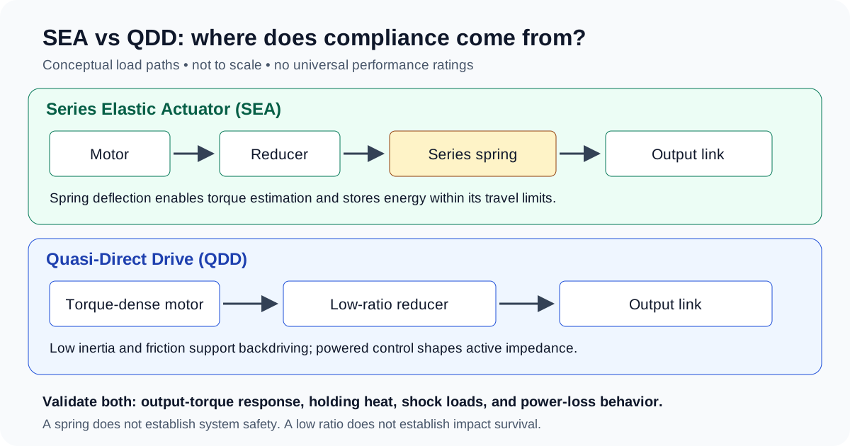
Conceptual diagram, not to scale. Ratios, spring placement, sensing layouts, and protection hardware vary by product.
3. Energy Efficiency, Regeneration, and Passive Locomotion Dynamics
Passive Mechanical Energy Storage vs Electric Regeneration
An SEA can store negative work as spring strain energy and return part of it later, provided the spring stiffness, available travel, and gait timing are suitable. The motor may still draw current to support load or regulate the spring's upstream position. Spring hysteresis, transmission friction, and control action reduce the useful return; there is no general near-zero copper-loss guarantee.
A QDD can convert negative joint work to electrical energy when its drive supports regeneration. Mechanical energy may also be dissipated or transferred through the mechanism rather than recovered. A simplified one-way model is:
E_to_battery = E_negative_joint × η_reverse_gear × η_generator × η_inverter × η_charge
This is one-way recovery, not round-trip efficiency. Returning that battery energy to useful motion introduces discharge and forward drivetrain losses. Battery state of charge, temperature, BMS limits, and bus voltage determine whether regeneration is accepted at all. Specify an energy-rated braking resistor or another validated dissipation path where required; transient suppression alone cannot absorb sustained regenerative energy.
For procurement, compare watt-hours at the battery over the same payload, trajectory, speed, and thermal conditions, recording starting and ending battery state and net spring energy. Stored spring joules alone cannot establish runtime improvement.
Continuous Static Holding Torque and Joule Heating
At zero joint speed, mechanical output power τ × ω is zero while motor current can remain substantial. To avoid mixing current conventions, this example uses balanced sinusoidal phase RMS current I_rms, phase-to-neutral resistance R_phase, and a torque constant K_t,rms defined per phase RMS ampere:
P_copper = 3 × I_rms² × R_phase
I_rms ≈ τ_joint / (N × K_t,rms × η_assumed)
For a balanced star winding measured between two terminals, R_line-line = 2 × R_phase, so the same loss is 1.5 × I_rms² × R_line-line. Do not substitute a drive's peak q-axis current without converting both current and torque-constant conventions. At standstill, η_assumed below is only an illustrative torque-transmission factor, not a measured power efficiency; actual static friction and holding behavior need testing.
Hypothetical Comparison: 80 N·m Holding Demand
These are invented parameter sets for arithmetic, not real candidates or verified continuous ratings. Resistance values are assumed at the same fixed winding temperature; neither set includes a brake or counterbalance.
| Assumed Input or Calculated Result | Low-Ratio Example A | High-Ratio SEA Example B |
|---|---|---|
| Joint holding demand | 80 N·m | 80 N·m |
Reduction ratio N | 8:1 | 80:1 |
| Line-to-line resistance | 0.12 Ω | 0.48 Ω |
K_t,rms | 0.14 N·m/A RMS | 0.08 N·m/A RMS |
| Assumed torque-transmission factor | 0.92 | 0.78 |
| Required motor torque | 10.87 N·m | 1.28 N·m |
| Calculated phase RMS current | 77.64 A | 16.03 A |
| Calculated copper loss | Approximately 1,085 W | Approximately 185 W |
The calculated ratio is approximately 5.86 for these assumptions. It is not an SEA-versus-QDD heat multiplier: the motors, resistances, torque constants, and ratios all differ. The spring itself does not reduce the equilibrium torque requirement.
Neither result proves that the joint can hold 80 N·m continuously. Predicting temperature or time to derating requires thermal resistance, thermal capacitance, temperature-dependent resistance, cooling, and component limits. Validate the winding, magnets, electronics, bearings, and touch surfaces in the installed condition.
For a candidate comparison, send the same holding interval and cooling boundary to our engineering team with your RFQ and request measured temperature traces alongside the torque ratings.
4. Component Engineering & Manufacturing Realities
Sourcing Realities of Custom Torsion Springs (SEA)
- Material and fatigue evidence: Request material traceability, heat treatment, geometry, stress analysis, and fatigue results at the intended mean torque, alternating torque, temperature, and surface condition. A material name or survival of
10⁷cycles is not proof of infinite life. Ask whether any cited spring standard actually covers the offered geometry; a machined planar flexure should not inherit approval from a helical-spring calculation. - Hysteresis and calibration: Request loading and unloading torque-angle curves across the working range and temperature envelope. Define acceptable nonlinearity, zero drift, and hysteresis from the control error budget. Calibration data must identify the unit and firmware revision.
- Sensor accuracy: With
k_sea = 800 N·m/rad, a0.05 N·mtorque increment corresponds to0.0000625 rad, or approximately12.9 arcsec. One count at that angle requires roughly 100,531 counts/revolution, but two-sensor quantization, noise, absolute accuracy, alignment, and drift determine usable torque resolution. Nominal bit depth alone does not establish accuracy.
Sourcing Realities of Low-Ratio Drives (QDD)
- Gears and bearings: Request backlash, output stiffness, bearing load limits, lubrication life, and load-spectrum evidence. Material, hardness, and gear quality are design-dependent; no single manufacturing grade guarantees shock survival.
- Cogging and friction: Measure unpowered breakaway torque with motor terminals open and brake released, then measure powered torque ripple across speed and temperature. These are different tests. Define limits relative to the application's interaction-force budget.
- Drive dynamics and regeneration: Request measured current-loop and output-torque responses, current-sensor accuracy, delay, and saturation behavior. Review bus-voltage protection against the worst credible negative-work event and the battery's charge-acceptance limits.
5. Application Matrix Across Robot Morphologies
These are shortlist hypotheses to test, not assignments of particular commercial robots to actuator types.
- Humanoid ankles: Consider SEA where spring travel and gait timing can provide useful impact filtering or energy return. Compare QDD where backdrivability and active control better meet the motion requirement; test the complete foot and leg load path.
- Humanoid knees: Evaluate squat and stair-climbing thermal duty as well as swing acceleration. High reduction, QDD, SEA, counterbalances, and linkage geometry all affect the result; topology alone cannot predict overheating.
- Hip yaw and roll: QDD is a candidate where low inertia and responsive torque control matter. Establish bandwidth from balance-control requirements and measured dynamics rather than a generic hertz target.
- Shoulders, elbows, and wrists: Compare mass, gravity holding, reach, collision exposure, and accuracy. Both physical compliance and active impedance can be useful in manipulation.
- Wearable exoskeletons: SEA can support torque sensing and physical compliance; QDD can support low-friction backdriving. Neither guarantees human safety. Analyze spring energy release, loss of support, brakes, range limits, and fault behavior within the applicable medical or wearable system assessment.
- Dynamic quadrupeds: Both approaches are viable. The 2016 ANYmal paper is a series-elastic quadruped reference, while the MIT Cheetah paper above is a low-impedance actuator reference. These platform examples do not establish a universal winner or current product specifications.
6. Manufacturing & Quality Engineering Checkpoints for OEM Sourcing
Use the following questions during supplier review. Acceptance values must be agreed for the application before sample testing.
Series Elastic Actuator (SEA) Factory Audit Criteria
- Is the spring linked to material and heat-treatment records, with an inspection method appropriate to its material and geometry?
- Do fatigue reports identify load spectrum, mean load, sample count, runouts, failures, and post-test stiffness change?
- Are torque-angle calibration, hysteresis, and thermal zero-offset results traceable to the supplied unit and firmware?
- Are spring travel, hard-stop behavior, replaceability, and overload inspection procedures documented?
Quasi-Direct Drive (QDD) Factory Audit Criteria
- Do gear and bearing reports state backlash, runout, lubrication, radial/axial loads, and duty conditions?
- Are unpowered cogging, backdrive friction, and powered torque ripple measured separately?
- Are continuous holding temperature traces separate from rotating torque-speed curves and time-limited peak ratings?
- Does the installed thermal test use the intended cooling interface, ambient, and limits for all critical components?
7. Sourcing & RFQ Checklist (Buyer Validation Worksheet)
Copy these evidence requests into the RFQ. There are no universal numerical pass limits in this worksheet. Freeze the load case, test procedure, acceptance limit, and responsibility with the supplier before issuing a pilot purchase order.
| Inspection Gate | Required Technical Deliverable | Acceptance Basis | Commercial & Sourcing Risk Addressed |
|---|---|---|---|
| 1. Spring life (SEA) | Traceable fatigue report with geometry, load spectrum, temperature, and sample count. | Agreed service cycles and allowable stiffness change; stated inspection and replacement interval. | Undocumented spring-life assumptions. |
| 2. Torque accuracy | Calibrated output-torque error, hysteresis, noise, and drift across the operating range. | Joint-level error budget, with full-scale versus reading-based error defined. | Incompatible sensing and control requirements. |
| 3. Control bandwidth | Output-torque frequency response and step response; include amplitude, fixture, inertia, bias torque, temperature, and delays. | Agreed tracking, phase/stability margin, and saturation limits under the same boundary conditions. | Comparing current-loop speed with joint force response. |
| 4. Continuous and peak thermal duty | Holding-temperature trace, rotating torque-speed data, and peak duration/recovery conditions. | Thermal equilibrium within declared limits for windings, magnets, drive, and bearings at installed cooling conditions. | Buying a peak rating as continuous performance. |
| 5. Backdriving and power loss | Breakaway/running torque with terminal and brake state recorded; fault-state test results. | Application friction budget and system-level loss-of-power requirements. | Unexpected drag, motion, or loss of support. |
| 6. Shock and overload | Representative impulse, direction, fixture, repetition count, and post-test inspection. | Agreed load spectrum without unacceptable permanent deformation, backlash growth, or sensor drift. | Treating one overload percentage as a fall-survival guarantee. |
| 7. Bus and regeneration | End-to-end latency/jitter under intended axis count and bus load; DC-bus energy-handling test. | Control timing budget, defined packet-loss response, and voltage limits with the intended power source. | Timing instability and regenerative overvoltage. |
8. Frequently Asked Questions (FAQ)
What is the primary operational difference between an SEA and a QDD?
An SEA adds an intentional compliant element in series with the load, allowing spring-deflection torque sensing and energy storage. A QDD uses relatively low reduction to reduce reflected inertia and support backdriving, with feedback control shaping active impedance. QDD passive mechanical transparency is distinct from powered software compliance.
Do QDD motors always overheat while holding a humanoid posture?
No. Low reduction can increase required motor torque and current for a given joint load, but motor torque constant, winding resistance, cooling, posture, brakes, and counterbalances determine the thermal result. The hypothetical 80 N·m example above is not a product rating or a general heat ratio.
Can an SEA match the force-control bandwidth of a QDD?
Possibly; the architecture name does not settle this. Spring stiffness, inertia, controller, torque amplitude, and whether the output is blocked or free affect the result. Request measured output-torque responses using the same load conditions and bandwidth definition.
Does an SEA make a medical exoskeleton safe during a fault?
No. The spring remains mechanically compliant within its travel, but it can release stored energy, reach a hard stop, or fail to support the wearer. Safety requires assessment of the complete system, including fault response, brakes, support, and motion limits. Industrial collaborative-robot guidance is not medical-device approval.
How does spring stiffness affect robot performance?
At a fixed torque, a softer spring deflects more and stores more energy, but needs more travel. At a fixed allowed deflection, a stiffer spring stores more energy and supports more torque. Stiffness also affects resonance and sensing sensitivity; select it against travel, fatigue, and control requirements rather than treating softer as universally better.
Which fieldbus should a sourcing team specify?
Specify cycle time, axis count, synchronization, end-to-end latency, fault response, and the controller's supported interfaces first. EtherCAT and CAN-FD are candidate technologies. A protocol name, nominal bitrate, or distributed-clock specification alone cannot guarantee application-level timing.
9. Authoritative Sources, Evidence Boundaries & Standards
- Pratt, G. A., & Williamson, M. M. (1995). Series elastic actuators. IROS '95, Vol. 1, pp. 399–406. Published paper, DOI: 10.1109/IROS.1995.525827. Foundational reference for intentional series elasticity and actuator impedance.
- Wensing, P. M., Wang, A., Seok, S., Otten, D., Lang, J., & Kim, S. (2017). Proprioceptive Actuator Design in the MIT Cheetah: Impact Mitigation and High-Bandwidth Physical Interaction for Dynamic Legged Robots. IEEE Transactions on Robotics, 33(3), 509–522. Published paper, DOI: 10.1109/TRO.2016.2640183. A specific low-impedance actuator design reference, not a rating for all QDD modules.
- Paine, N., Oh, S., & Sentis, L. (2014). Design and control considerations for high-performance series elastic actuators. IEEE/ASME Transactions on Mechatronics, 19(3), 1080–1091. Published paper, DOI: 10.1109/TMECH.2013.2270435. Reference for SEA design and control trade-offs.
- Hutter, M., Gehring, C., Jud, D., Lauber, A., Bellicoso, C. D., Tsounis, V., et al. (2016). ANYmal - a highly mobile and dynamic quadrupedal robot. IROS, pp. 38–44. Published paper, DOI: 10.1109/IROS.2016.7758092. A specific quadruped platform reference; it does not prove the specifications of later ANYmal generations or third-party products.
- International Organization for Standardization (ISO). ISO/TS 15066:2016 Robots and robotic devices — Collaborative robots. Official catalog record. The record describes guidance for collaborative industrial robot systems. It explicitly excludes non-industrial robots; it does not certify an actuator, humanoid, or medical exoskeleton. Confirm the applicable standards and editions for the actual deployment.
Evidence boundary: The calculations use stated hypothetical inputs and elementary spring, inertia, and copper-loss models. They are not physical test results, customer cases, or supplier capability evidence. The sources establish literature context; they do not supply universal acceptance limits. Review the comparison again when candidate hardware, firmware, duty cycle, or applicable requirements change.
10. Engineering Support & RFQ Sourcing
To compare candidate SEA and QDD modules, submit your joint torque-speed-time profile, holding intervals, impact load assumptions, dimensional envelope, cooling interface, communication needs, prototype quantity, and delivery location.
Ask the supplier to identify what is standard, what requires customization, and which calibration, thermal, fatigue, and dynamic test records are available for the quoted configuration. Agree missing validation work, cost, and lead time before ordering; this article does not promise a particular certificate or manufacturing capability.
- Direct Engineering Inquiries: [email protected]
- Product Catalog: Browse Robotic Joint Modules
- Technical Sourcing Consultation: Request an Application Engineering Review
Author

More Posts
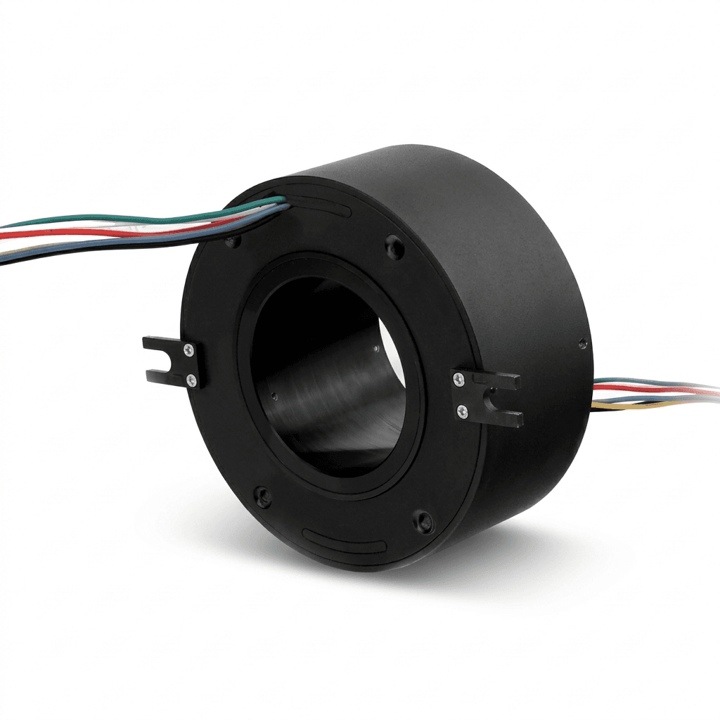
Hollow-Shaft vs Solid-Shaft Robot Joint Modules: A Sourcing Guide (2026)
An engineering and procurement guide to evaluating hollow-shaft versus solid-shaft robotic joint modules for humanoid, cobot, and industrial robot arms.

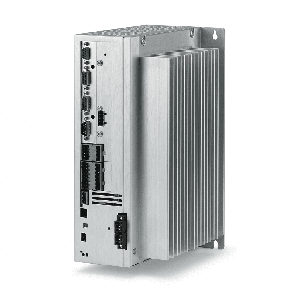
Robot Joint Module Thermal Management & Derating Guide
A comprehensive guide for engineers and procurement teams on understanding thermal derating, continuous torque limits, and heat mitigation strategies in robotic joint modules.
Strain Wave vs. Cycloidal Drive in Robot Joint Modules: Sourcing Guide
A comprehensive engineering and procurement guide comparing strain wave and cycloidal drives in robotic joint modules. Evaluate payload, backlash, and costs.