
Engineering decision guide
Updated
AGV Arm Joint Actuator Control Guide
Choose feedback and validate braking, timing and stopping.
For controls engineers integrating arms on mobile platforms.
Reviewed by Robotic Joint Module. Engineering analysis; no hardware-test or certification claim.
Four decisions before tuning
Decision 1
Choose the operating envelope first
Separate docked manipulation, stowed travel and simultaneous base–arm motion. Moving the base changes the disturbance model; select tolerances and test cases for each mode.
[S1][S2][S3]Decision 2
Match feedback to mechanical compliance
A load encoder can observe output position that a motor encoder cannot. Dual feedback is an option to validate against measured compliance, not a guarantee of repeatability or stability.
[S6]Decision 3
Budget energy and timing separately
Check where braking energy can go, then measure command deadlines under navigation load. Neither nominal battery voltage nor synchronized device clocks establish those limits.
[S7][S8][S9]Decision 4
Validate stopping at system level
Select stop functions from the risk assessment and hardware capability. STO removes torque production; it does not hold a gravity-loaded arm or certify the integrated vehicle.
[S1][S2][S3][S4]Evidence, method and limits
Primary sources below were checked on . Standards catalogues establish edition and scope; the full clauses were not audited here. Manufacturer documents establish behavior for their specified products. Calculations and workflow recommendations are engineering analysis, not measured product performance.
| Source / edition | Supported use | Boundary |
|---|---|---|
[S1] ISO 3691-4:2023 — driverless industrial trucks Published 2023-06; revision in development | Public catalogue scope includes AGVs and AMRs. | Catalogue access does not verify individual clauses or certify a machine; assess application scope. |
[S2] ISO 10218-1:2025 — industrial robots Edition 3, 2025-02 | Robot safety scope; excludes mobility hazards of robots on mobile platforms. | Robot-level conformity alone cannot establish mobile-system safety. |
[S3] ISO 10218-2:2025 — robot applications and cells Edition 2, 2025-02 | Application and cell integration scope. | Public catalogue establishes scope, not a complete mobile-manipulator compliance route. |
[S4] Kollmorgen — Stop and Emergency Stop Function Manufacturer guidance, 2013; checked 2026-11 | Explains Category 0 and 1 emergency stopping and risk-based selection. | Historical explanatory guidance; confirm current standards and the installed safety manual. |
[S5] CAN in Automation — CiA 402 series Parts 2/3 revision 5.0.0, 2024-02 | Drive state machine and motion profile; distinguishes revisions and optional functions. | Profile support does not guarantee every mode or interchangeable PDO maps. |
[S6] Synapticon — Dual Loop Cascaded Position Control Legacy firmware 4.1; unmaintained | Example: motor encoder for commutation/velocity, output encoder for position; gear ratio configuration. | Architecture example only. Verify current firmware feedback paths and scaling. |
[S7] Synapticon — 48 V braking chopper specifications Online product specifications, checked 2026-11 | Specific product documents threshold overshoot and cooling-dependent continuous power. | Product-specific values are not universal BMS limits or resistor recommendations. |
[S8] Beckhoff — XFC distributed clocks Online technology reference, checked 2026-11 | Describes sub-microsecond device clock synchronization. | Device clock accuracy is distinct from host scheduling and sensor-to-actuator latency. |
[S9] ros2_control — Jazzy Controller Manager ROS 2 Jazzy online documentation, checked 2026-11 | Describes scheduling, kernel setup and execution-time/periodicity diagnostics. | Real-time setup improves timing; it does not certify a safety stop or guarantee application deadlines. |
[S10] Kollmorgen AKD2G — cyclical setpoints and actual values Online AKD2G implementation reference, checked 2026-11 | Examples of object addresses and data widths, including INT16 target torque. | Use the actual drive ESI, dictionary and firmware for units, supported mapping and axis offsets. |
[S11] SEW-EURODRIVE — CiA402 output objects Manual edition 2023-07 | Lists target position, velocity, torque and optional offsets as distinct outputs. | Mapping availability is specific to this product family and firmware. |
Published evidence
Standards scope and documented drive features have named sources. Match every implementation to a firmware and hardware revision.
Idealized models
Rigid point-mass torque, a linear two-inertia spring and ideal capacitor storage show dependencies. They omit real losses and nonlinearities.
Measurements still needed
Friction, stiffness by load, thermal derating, brake timing and battery acceptance have no universal values in this guide. Request data or measure them.
Scope: electrically driven articulated arms on industrial AGV/AMR platforms. Public-access robots, personnel lifting and special environments need additional requirements. This report does not define a certified safety architecture or substitute numerical acceptance limits for your task.
Model base motion in joint coordinates
A translating or rotating base changes link accelerations relative to an inertial frame. Compute each link contribution in a consistent frame before projecting it onto a joint axis. The scalar example below is a first-principles estimate, not a complete mobile-manipulator model.
Coupled-model bookkeeping
Mmm(q)q̈m + Mmb(q)q̈b + hm(q, q̇) = τm
qm: arm coordinates; qb: admissible base coordinates; h includes gravity, velocity-dependent and modeled friction terms. Base constraints and actuator mapping belong in the full model. Do not insert unfiltered IMU specific force as world-frame acceleration or count gravity twice.
Worked point-mass example
|τaxis| = |êaxis · (r × m a)|
τ = 5 × 1.5 × 0.85 = 6.375 N·m
Assume 5 kg, 1.5 m/s² base acceleration and a perpendicular lever arm of 0.85 m about the selected axis. The sign depends on geometry. This is the additional point-mass disturbance; link mass, base rotation and gravity are excluded. Horizontal reach alone does not define a pitch-joint moment arm for horizontal acceleration.
| Mode | Disturbance to evaluate | Decision / measurement |
|---|---|---|
| Docked manipulation | Residual platform compliance and docking motion | Begin with supported stationary operation; measure pose repeatability after docking. |
| Stowed transport | Acceleration, cornering and floor-induced motion | Validate holding capacity, swept envelope and platform stability with the arm stowed. |
| Simultaneous base–arm motion | Translational, angular and posture-dependent coupling | Use timestamped base state and complete link dynamics; compare feedforward on/off in a controlled test. |
The three modes are proposed test categories. Their use does not establish safety or a tracking improvement. Vehicle and robot scopes remain distinct. [S1][S2][S3]
Tune from the inner loop outward
Confirm the drive architecture before selecting host commands. In a cascaded scheme, commission current control before velocity, then position. PWM frequency, sampling rate and closed-loop bandwidth are different quantities. No fixed bandwidth ratio or auto-tune recipe is established for all AGV arms. [S6]
| Step | Inspect | Continue when |
|---|---|---|
| 1 · Motor and sensors | Phase/encoder alignment, current scaling, direction and limits | The supplier commissioning procedure passes with supported hardware and restrained motion. |
| 2 · Current / torque | Current response, saturation and drive-side limits | Measured response follows the drive procedure; no oscillation or current-limit excursions in the test envelope. |
| 3 · Velocity and compliance | Frequency response, resonance and filtering | Stability margins and noise sensitivity meet the chosen design criteria across required payloads. |
| 4 · Position / trajectory | Following error, settling, backlash and jerk | Measured path and settling errors meet the task limits without hiding saturation. |
| 5 · Mobile disturbance | Timestamped IMU/odometry, frame transforms and torque feedforward | A repeatable comparison demonstrates benefit without exceeding torque, tracking or stability limits. |
Set numerical exit criteria before each test. Motor-current torque estimates include model error and transmission losses; they are not automatically calibrated load torque or a safety-rated collision signal. Feedback and limit semantics depend on the drive. [S5][S10]
Use dual feedback where the mechanics justify it
One documented architecture uses the motor encoder for commutation and velocity and the output encoder for position. It can observe transmission-related position error, while introducing additional scaling, filtering and stability work. The source is a legacy implementation example, not a universal requirement. [S6]
Motor-side measurement
Useful for rotor commutation and velocity feedback. It does not directly measure output deflection, lost motion or downstream structure.
Output-side measurement
Observes output angle at the encoder mounting point. It does not measure the full tool pose, remove gearbox compliance or guarantee micron-level repeatability.
Two-inertia calculation — assumed values, not measured stiffness
Jm,out = Jm N²; fanti = √(K/JL)/(2π); fres = √(K(1/Jm,out + 1/JL))/(2π)
For a linear, undamped spring between two inertias, assume K = 14,000 N·m/rad, Jm,out = 0.45 kg·m² and JL = 0.15 kg·m². The motor-response model gives fanti ≈ 48.6 Hz and fres ≈ 56.1 Hz. All quantities are referred to the output side.
These are ideal model frequencies. Real bearings, structure, damping, friction and posture can move or add modes. They do not determine a notch center, depth, Q or loop bandwidth. Identify the installed plant and validate stability before applying a filter.
Budget regenerative energy before choosing protection
A battery-fed drive may return energy during deceleration or downward motion. Establish whether the source accepts that energy in every relevant operating state. A chopper is one possible path, alongside a regenerative source, shared loads or storage. Its trigger threshold is not necessarily the highest voltage seen on the bus. [S7]
| Quantity | Assumption / equation | Result |
|---|---|---|
| Rotational energy | J = 0.6 kg·m²; ω = 3.5 rad/s; E = ½Jω² | 3.675 J |
| Capacitor headroom | C = 1,500 µF; 48 → 56 V; ΔE = ½C(56² − 48²) | 0.624 J |
| Excess beyond headroom | Lossless model, no source absorption: max(0, 3.675 − 0.624) | 3.051 J (83.0% of initial energy) |
| Initial mechanical braking power | Linear deceleration in 0.12 s: Pinitial = Jω²/t | 61.25 W; average over the stop = 30.625 W |
56 V is an assumed calculation ceiling, not a recommended chopper setting. This model excludes gravity release, other axes, electrical losses and battery acceptance. It shows an energy gap under those assumptions; it does not predict a trip time, bus overshoot or required resistor.
Voltage window
Use actual pack, drive and chopper limits, with tolerances and overshoot. A nominal 24 V or 48 V rating does not identify a BMS threshold.
Peak and pulse limits
A resistor must satisfy the chopper minimum resistance and current limit as well as instantaneous voltage, pulse energy and insulation limits.
Repeated operation
Average dissipation depends on energy per cycle and repetition period, plus cooling. A fixed percentage of peak power is not a continuous rating.
For example, the specific S7 product lists possible transient rise up to 5 V above its activation threshold and cooling-dependent continuous power. Read those conditions with the installed hardware data; no generic 1.8–3.3 Ω selection follows from this page. [S7]
Separate control modes, synchronization and PDO layout
| Mode | Normal command / loop ownership | Integration cost and boundary |
|---|---|---|
| CSP · mode 8 | Target position; drive closes position, velocity and current loops | Lower host feedback burden. Check optional feedforward support and interpolation behavior. |
| CSV · mode 9 | Target velocity; host may close position, drive closes velocity/current | Host must handle position feedback, timing and limits consistently. |
| CST · mode 10 | Target torque; host implements required higher-level control | Greater host control burden: state feedback, torque scaling, limits and fault behavior require explicit validation. |
These are architecture choices, not performance rankings. Supported functions vary by drive and firmware. A 1 ms cycle is a candidate design point, not a prerequisite for every application. For CANopen, check PDO segmentation and bus utilization; for EtherCAT, check process data, Sync configuration and master execution time. [S5][S11]
Device clock synchronization
Distributed clocks align device time bases. The cited Beckhoff technology describes sub-microsecond synchronization; this is not a guarantee of host command latency. [S8]
Host deadline performance
Measure read/update/write execution and worst-case periodicity while perception and navigation run. Jazzy documents SCHED_FIFO setup and diagnostics; a real-time kernel alone does not establish deadlines. [S9]
Example 32-bit-position object set
Check the installed ESI, object dictionary and scaling. The following is an integration checklist using common widths, not a mandatory or universal mapping. Newer profile revisions can add other widths. [S5][S10][S11]
| Index | Width / direction | Purpose and check |
|---|---|---|
| 0x6040 / 0x6041 | UINT16 / UINT16; Rx / Tx | Controlword / statusword. Decode state and acknowledge transitions before motion. |
| 0x6060 / 0x6061 | INT8 / INT8; Rx or SDO / Tx or SDO | Requested / displayed mode; verify support and acknowledgement. |
| 0x607A | INT32; Rx | CSP target position. Verify configured position units. |
| 0x60FF | INT32; Rx | CSV target velocity. Verify configured velocity units. |
| 0x6071 | INT16; Rx | CST target torque. Verify rated-torque reference and scaling. |
| 0x60B1 / 0x60B2 | INT32 / INT16; optional Rx | Velocity / torque offsets. Confirm support, units and interaction with the selected mode. |
| 0x6064 / 0x606C | INT32 / INT32; Tx | Position / velocity actual values. Encoder source and coordinate scaling are drive-specific. |
| 0x6077 / 0x60F4 | INT16 / INT32; Tx if supported | Torque / following-error actual values. Verify estimation method and diagnostic semantics. |
| Temperature / fault diagnostics | Vendor-specific; mapping varies | No portable 0x2050:01 temperature index or generic watchdog fault code is assumed. |
Example CSP Rx payload: 13 bytes
0x6040 (2) + 0x6060 (1) + 0x607A (4) + 0x60B1 (4) + 0x60B2 (2)
Example Tx payload: 17 bytes
0x6041 (2) + 0x6061 (1) + 0x6064 (4) + 0x606C (4) + 0x6077 (2) + 0x60F4 (4)
Counts exclude protocol overhead and padding. Confirm whether entries can be grouped and mapped; CANopen Classic may require multiple PDOs. A CST configuration needs the 0x6071 target; do not reuse the CSP-only list unchanged. Ordinary controlword Quick Stop is not itself evidence of a safety-rated function.
Reproduce the example with your assumptions
Use this optional calculation after defining the model. It reports arithmetic and assumptions, and deliberately leaves hardware and control settings to the measured plant and supplier specifications.
Check the torque and energy arithmetic
Two independent idealized models: one point mass under base acceleration, and one rotating inertia under linear deceleration. Enter measured inertia separately. Outputs are estimates for discussion, not tuning or hardware selection. The assumed voltage ceiling must come from your drive, battery and chopper specifications, including tolerance and overshoot.
Fixed example: editing and copying require JavaScript. The displayed values use the example inputs below; they are not your project results. You can still read the methods and request a manual review.
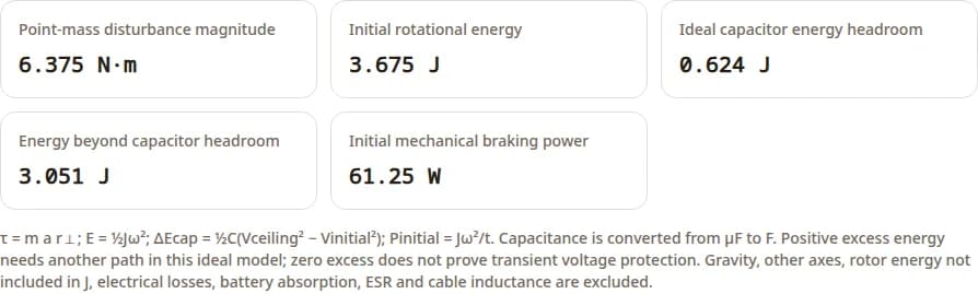
- Point-mass disturbance magnitude
- 6.375 N·m
- Initial rotational energy
- 3.675 J
- Ideal capacitor energy headroom
- 0.624 J
- Energy beyond capacitor headroom
- 3.051 J
- Initial mechanical braking power
- 61.25 W
τ = m a r⊥; E = ½Jω²; ΔEcap = ½C(Vceiling² − Vinitial²); Pinitial = Jω²/t. Capacitance is converted from µF to F. Positive excess energy needs another path in this ideal model; zero excess does not prove transient voltage protection. Gravity, other axes, rotor energy not included in J, electrical losses, battery absorption, ESR and cable inductance are excluded.
Calculation text and assumptions
AGV joint illustrative calculation — assumptions, not validated hardware settings
Point mass (kg): 5
Perpendicular moment arm (m): 0.85
Base acceleration magnitude (m/s²): 1.5
Output-referred inertia J (kg·m²): 0.6
Initial joint speed magnitude (rad/s): 3.5
Linear deceleration duration (s): 0.12
Bus capacitance (µF): 1500
Initial bus voltage (V): 48
Assumed bus ceiling (V): 56
Point-mass disturbance magnitude: 6.375 N·m
Initial rotational energy: 3.675 J
Ideal capacitor energy headroom: 0.624 J
Energy beyond capacitor headroom: 3.051 J
Initial mechanical braking power: 61.25 W
Independent torque and energy examples. Inertia is entered separately, not derived from the point mass.
Linear deceleration, lossless rotation, no gravity release or other axes. Actual energy flow depends on losses and source absorption.
Bus ceiling is an assumption, not a BMS or drive rating. No resistor, PID or safe stopping setting is selected.
Define safety functions at the integrated-system boundary
ISO 3691-4 addresses driverless industrial trucks. ISO 10218-1 addresses the industrial robot and explicitly excludes mobility hazards on mobile platforms; Part 2 addresses robot applications and cells. Treat their public scope descriptions as starting points for applicability analysis, not a complete compliance recipe. [S1][S2][S3]
| Function / category | Intended behavior | What it does not establish |
|---|---|---|
| STO / Category 0 arrangement | Torque-producing drive power is removed; motion can coast or move under gravity. | No mechanical holding, brake engagement or electrical isolation guarantee follows from STO alone. |
| SS1 / Category 1 arrangement | Controlled deceleration followed by torque removal, implemented per the safety manual. | No universal stop time or stopping distance. Loss of supply/control and deceleration failure need defined responses. |
| SS2 / safe operating stop | Controlled stopping with a monitored energized standstill arrangement. | Not an emergency-stop replacement; restart and access conditions require separate validation. |
| SBC and mechanical brake | A safety-related brake-control output can command a compatible brake. | A commanded brake is not proof of holding capacity, wear state or successful engagement. |
Select Category 0 or 1 from the risk assessment
Neither category is universally forbidden or sufficient. Assess which stopping behavior minimizes the actual hazard, including gravity-loaded axes, traction stopping, payload retention, power loss and failed deceleration. Validate brake sequencing and failure response against the specific safety manual. No 120–180 ms ramp, fixed engagement speed or SIL/PL rating is prescribed here. [S4]
The safety chain must cover the vehicle and arm swept envelope, load retention, protective sensing, stop performance and restart interlocks. Ordinary ROS or fieldbus fault handling does not certify this chain. Determine required performance and validate achieved performance for each safety function with the relevant current standards and hardware documentation.
Three hypothetical decision scenarios
These exercises illustrate how to choose a test, not customer deployments or measured performance claims. No improvement percentage, service history or product qualification is implied.
Docked machine tending
Premise: The base parks before a 5 kg payload transfer; machining alignment matters more than travel-time arm motion.
Test: Measure docking pose and residual compliance, tune supported stationary operation, then verify stowed travel separately.
Decision: Keep simultaneous manipulation disabled unless the extra cycle-time value justifies a separate validation program.
Lowering near full battery
Premise: The pack may reject charging while a vertical motion releases potential energy.
Test: Add gravity energy and simultaneous axes to the rotational budget; test the allowed bus window in a controlled setup.
Decision: If the source cannot absorb the pulse, evaluate a manufacturer-approved dissipation or storage path and its repeated-duty limits.
Arm motion during travel
Premise: The task requires a stable tool pose while the platform accelerates.
Test: Record timestamped base state, joint state, tool pose and timing. Compare a constrained model-based feedforward trial with baseline.
Decision: Accept only if measured tracking, thermal, bus, platform-stability and safety criteria all pass over the declared envelope.
Failure modes and diagnostic tradeoffs
| Observed symptom | Possible cause / uncertainty | Next measurement and mitigation |
|---|---|---|
| Oscillation after payload change | Mechanical mode, gain margin, scaling error or saturation; sound alone cannot identify it. | Compare encoder traces and frequency response across postures. Reduce the test envelope before retuning. |
| Bus rises during descent | Energy has no sufficient return path, or local transients exceed a device limit. | Capture bus voltage/current at the drive and pack; check contactor state, charge acceptance and chopper limits. |
| Tool sways during travel | Platform tilt/compliance, timestamp errors or an incomplete dynamic model. | Compare tool motion with base state in a consistent frame; constrain travel or add validated compensation. |
| Deadline faults under perception load | Scheduling, blocking I/O, network or device-watchdog configuration. | Measure worst-case execution and frame timing with the full workload; use the actual drive fault dictionary. |
| Temperature rises in an enclosure | Heat rejection and RMS duty differ from the rated test conditions. | Measure winding/drive/ambient temperature and current over the duty cycle. Obtain the actual derating curve. |
| Axis moves after torque removal | Gravity, brake capacity/delay, sequencing or a mechanical fault. | Use the validated holding and stopping test procedure; verify independent failure response before operation. |
These are diagnostic hypotheses, not verified failure diagnoses or universal thresholds. Additional feedback, a faster bus and a chopper each add integration, testing and thermal cost; choose them only when the measured failure mechanism and task justify them. [S4][S6][S7][S9]
Commissioning evidence and next actions
Set numerical limits from your task and component ratings before testing. Record payload, posture, base motion, battery state, temperature and software revisions with every trace. An empty evidence field is an unresolved commissioning item.
Controls engineer
Record sign/scaling checks, measured plant response, following-error and settling limits, saturation traces and feedforward comparisons. Include the worst required payload/posture.
Electrical engineer
Document voltage windows, battery acceptance, bus transients, simultaneous-axis energy, chopper pulse/current limits and thermal steady-state behavior.
Software integrator
Freeze ESI/firmware, identify every encoder source and object unit, verify state transitions, and record worst-case sensor age and read/update/write deadlines under full compute load.
Safety lead
Document applicable standards, risk-assessed stop functions, load holding, power-loss response, stopping envelope, failure tests and deliberate restart behavior.
Suggested release record: test ID → configuration and limit → measured trace → pass/fail → owner. Release only the operating modes for which the required evidence is complete; the arithmetic tool does not issue a commissioning pass.
Questions that change the integration decision
Architecture and tuning
Can I keep the existing controller when mounting an arm on an AGV?
Possibly. Start with docked motion and stowed travel as separate modes. Compare tracking, structural vibration and tip stability across the required base acceleration envelope before enabling simultaneous motion. A fixed-base tuning result alone does not validate mobile operation.
Does a dual encoder remove gearbox deflection?
It measures position on both sides of the transmission; it does not remove mechanical compliance. Feedback gains, filtering, sensor alignment and payload still determine stability and accuracy. The legacy Synapticon architecture example is source S6; current firmware must be checked.
What PID bandwidth or notch frequency should I use?
Payload and reach alone cannot determine gains or notch settings. Use the drive commissioning procedure, identify the frequency response in the allowed test envelope, then check margins and tracking across payload and posture. The two-mass calculation is a model, not an identified plant.
When is base acceleration feedforward useful?
When measured base motion contributes materially to tracking error and synchronized motion states are available. Validate coordinate frames, timestamps, gravity treatment and torque limits first. No error-reduction percentage is established by this guide.
Power and integration
Is 58.4 V a universal 48 V battery cutoff?
No. A nominal voltage does not identify chemistry, series count, BMS settings, state of charge or charge acceptance. Use the pack and drive specifications, including temperature, contactor state and tolerances, to define the operating window.
Do all AGV arms need a braking resistor?
No. Regeneration may be absorbed by the battery, a regenerative supply, shared loads, capacitors or a chopper. Assess the worst operating state, including a full battery or an open contactor. Source S7 is a product example, not a requirement for all drives.
Can this calculator select a chopper or continuous resistor rating?
No. It estimates ideal point-mass torque and rotational energy. Resistor selection also needs chopper minimum resistance and peak current, voltage overshoot, pulse-energy curves, repetition rate, cooling, protection and the complete multi-axis energy balance.
Is 1 kHz EtherCAT mandatory for mobile manipulation?
No universal rate is established here. Choose and verify the update period from the task dynamics, latency budget, supported drive modes and network load. Distributed-clock synchronization and host scheduling are different measurements; see S8 and S9.
Should I choose CSP, CSV or CST?
Use CSP when the drive closes position control, CSV when the host closes position around a velocity command, and CST when the host supplies torque commands with the required feedback and limits. Confirm each mode in the installed firmware; CiA 402 naming alone does not prove support.
Are the example PDO layouts portable between drives?
No. The byte counts describe the listed example entries only, excluding protocol overhead and padding. Verify supported entries, units, mapping limits and encoder sources against the actual ESI and firmware before enabling motion; see S5, S10 and S11.
Safety and acceptance
Must every emergency stop use SS1?
No. Emergency stopping uses risk-assessed Category 0 or 1 arrangements. A controlled stop depends on available power and functioning controls. The safety design must also address loss of power, brake failure and failed deceleration; no universal ramp time is specified here.
Does STO hold the payload?
No. STO prevents torque generation and is not a mechanical holding function. A gravity-loaded axis needs a validated load-holding strategy, with brake capacity, engagement delay, wear and fault response checked in the installed system.
Does a CiA 402 Quick Stop command constitute a safety function?
An ordinary motion-profile command does not establish a safety-rated stop. Use the documented certified safety interface and independently validated safety chain for the required function. ros2_control error handling is not a substitute for that chain.
Which measurements should accompany a supplier review?
Send joint-coordinate torque and speed limits, inertia by posture, bus voltage traces, battery charge-acceptance limits, current and temperature logs, encoder configuration, firmware/ESI revisions, deadline measurements and the intended stop/holding concept. Define numerical acceptance limits from the actual task.
Are the scenarios in this guide measured customer deployments?
No. They are hypothetical decision exercises with declared assumptions. The numerical examples are reproducible ideal-model calculations, not observed field results, product ratings or compliance evidence.
What remains unknown before commissioning?
Application-specific friction, stiffness, thermal capacity, charge absorption, brake dynamics and worst-case stopping behavior require supplier data or tests. This guide provides no empirical substitute for those measurements.
Prepare an engineering review package
Send the intended motion modes, payload/posture envelope, joint torque/speed data, feedback architecture, battery and bus limits, timing traces and safety requirements. Ask the supplier to identify missing measurements, supported firmware features and the exact rating conditions before selecting modules.
Inquiry Email
Send target torque/speed, protocol, quantity, and delivery location.