
Published & reviewed
AGV Arm Joint Actuator Definition
A controlled motion unit for an arm joint on an AGV or AMR. Check its integration boundary and estimate base disturbance.
Request engineering reviewCheck your actuator specification
Choose an axis to estimate base disturbance; then edit the ratings.
Presets are fictional examples, not product ratings. Changing axis preserves your subsystem declarations.
Fixed example: interactive controls require JavaScript. Read the method below or request a manual engineering review.
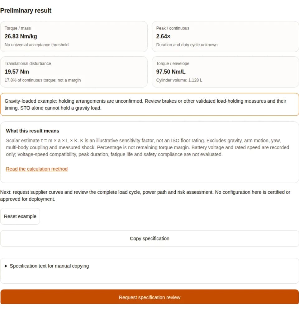
Preliminary result
- Torque / mass
- 26.83 Nm/kg
- No universal acceptance threshold
- Peak / continuous
- 2.64×
- Duration and duty cycle unknown
- Translational disturbance
- 19.57 Nm
- 17.8% of continuous torque; not a margin
- Torque / envelope
- 97.50 Nm/L
- Cylinder volume: 1.128 L
Gravity-loaded example: holding arrangements are unconfirmed. Review brakes or other validated load-holding measures and their timing. STO alone cannot hold a gravity load.
What this result means
Scalar estimate τ = m × a × L × K. K is an illustrative sensitivity factor, not an ISO floor rating. Excludes gravity, arm motion, yaw, multi-body coupling and measured shock. Percentage is not remaining torque margin. Battery voltage and rated speed are recorded only; voltage-speed compatibility, peak duration, fatigue life and safety compliance are not evaluated.
Read the calculation methodNext: request supplier curves and review the complete load cycle, power path and risk assessment. No configuration here is certified or approved for deployment.
Request a manual engineering reviewWhat is an AGV arm joint actuator?
Published and maintained by Robotic Joint Module. Method review: 2026-11-01. This supplier-authored guide covers specification screening; hardware test results and independent certification are outside its evidence.
An AGV arm joint actuator is the controlled motion unit that rotates a link of an articulated arm carried by an automated guided vehicle or autonomous mobile robot. It combines torque generation with the transmission, feedback, output support and control functions allocated to that joint. The integration boundary varies by product. “AGV arm joint actuator” describes an application, not a standards-defined eight-part certification class.
A3 describes the combined mobile platform and industrial manipulator as an IMR Type C. That system classification does not prescribe a particular reducer, bearing, encoder count or inverter location. [S10][S4]
Choose the integration boundary first
A frameless motor kit still needs bearings, mechanics, feedback and a drive allocated by the designer. A module packages some of those responsibilities.
[S9]Evaluate the moving platform as part of the load
Base acceleration changes forces at the joint; the scalar checker estimates only one term. A complete arm model must include posture, gravity and angular base motion.
[S1][S8]An illustrative integration architecture
This diagram shows one possible compact module. A hollow bore, integrated drive or cross-roller bearing can simplify packaging, but alternatives can be valid. Confirm the actual assembly drawing and responsibility split before comparing prices. [S9]
Eight functions to inventory, with evidence to request
| Function | Possible implementation | Evidence needed |
|---|---|---|
| Motor | Torque generation; frameless or housed. | Voltage-specific torque-speed curves, current convention, continuous cooling condition. |
| Transmission | Strain-wave, cycloidal, planetary or direct drive. | Ratio, efficiency, stiffness, lost motion and allowable repeated / momentary loads. |
| Feedback | Motor feedback; output sensing where required. | Resolution is not accuracy. Verify alignment, homing, deflection observability and tuning. |
| Holding arrangement | Brake, counterbalance or another validated measure for gravity loads. | Holding capacity, closing delay, wear and emergency-stop duty are separate checks. |
| Servo drive | Integrated electronics or external amplifier. | Supply window, current limits, regeneration path, interface and fault behavior. |
| Output support | Cross-roller or another validated bearing arrangement. | Combined radial / axial / moment loading, static margin, mounting and lubrication. |
| Thermal monitoring | Winding and electronics sensors as specified. | Sensor location, lag, allowable temperatures and mounted duty-cycle derating. |
| Safety interface | Required functions allocated by the system assessment. | Exact function, certified capability, wiring, diagnostics and validation records. |
A checkbox records an unverified declaration. Leave an item unchecked when it is unknown, external or inapplicable, then document the reason in the RFQ. Never count inventory completeness as an acceptance test. Motor integration: [S9] Bearing support: [S8] Safety functions: [S5][S11]
Calculation method, reproducible example and limits
τ_est = m × a × L × K; density = T_cont / actuator mass; envelope = π × (OD / 2)² × axial length / 1,000,000 L
| Quantity | Input / result | Interpretation |
|---|---|---|
| Supported effective mass / lever / base acceleration | 14.5 kg / 0.75 m / 1.2 m/s² | L is perpendicular to the acceleration force about the selected axis. Mass is the supported assembly, not just payload. |
| Illustrative sensitivity factor | K = 1.5 | Chosen assumption, not a floor rating or a measured impact multiplier. |
| Estimated translational disturbance | 14.5 × 1.2 × 0.75 × 1.5 = 19.575 Nm | 17.8% of the illustrative 110 Nm continuous rating; this is not available margin. |
| Envelope and torque density | OD 130 mm; length 85 mm; 4.1 kg; 1.128224 L | 26.83 Nm/kg and 97.50 Nm/L; envelope excludes protrusions unless dimensions include them. |
| Peak ratio | 290 / 110 = 2.636× | Peak duration, duty cycle and operating speed remain unconfirmed. |
The simplified model excludes gravity, arm acceleration, external contact, yaw acceleration, centripetal and Coriolis terms, and structural vibration. A zero mass, lever or base acceleration makes this term zero; it does not make total joint torque zero. Do not subtract its percentage from 100% to infer safe capacity.
For a rigid point observed in a rotating base frame, the kinematic identity is a_abs = a_base + α × r + ω × (ω × r) + 2ω × v_rel + a_rel. Calculating an actual joint torque then needs signed force/moment projections and the arm dynamics. This identity is engineering method commentary, not a model implemented by the checker.
| Boundary | Calculated or recorded | Required next step |
|---|---|---|
| Load | One translational disturbance magnitude | Full posture-dependent gravity and torque-speed cycle; measure base motion. |
| Power | Nominal battery voltage and rated speed recorded only | Supply extremes, winding curves, drive current limits and BMS acceptance. |
| Packaging | Cylindrical envelope and nameplate torque ratios | CAD, protrusions, mounting stiffness, cable bend and assembly tolerances. |
| Reliability / safety | Subsystem declarations only | Bearing and transmission calculations, validation tests and applicable certificates. |
Low-voltage supply, thermal path and regeneration
24 V, 48 V and 60 V are example nominal battery choices. None defines a universal operating window. Compare actual minimum, maximum and transient bus voltage with the winding-specific torque-speed curve and drive limits. Supply voltage alone cannot prove output torque at speed. For motor-current and copper-loss calculations, state phase versus line quantities and RMS versus peak conventions consistently. [S9]
| Quantity | Assumption / calculation | Limit |
|---|---|---|
| Capacitor energy headroom | C = 2,200 µF; 51.2 → 56.5 V; ΔE = ½C(V₂² − V₁²) = 0.627891 J | Both voltages are hypothetical. Not a BMS trip or clamp recommendation. |
| Rotational kinetic energy | J = 0.08 kg·m² at the same reference shaft as ω = 9 rad/s; E = ½Jω² = 3.24 J | All reflected inertia and speeds must use the same shaft reference. |
| Difference if all kinetic energy reaches the bus | 3.24 − 0.627891 = 2.612109 J | Lossless illustration; excludes gravity release, base energy and other axes. |
| Thermal / chopper selection | Not determined | Need time waveform, repeated pulses, minimum resistor value, peak current, cooling and BMS coordination. |
Continuous holding can heat a sealed arm even at zero speed. Cooling assumptions must include housing contact, ambient temperature, mounting and heat from the drive and transmission. Use the supplier’s tested derating curve; a universal thermal resistance or magnet temperature limit cannot qualify every module. [S9]
Compare integration choices by engineering responsibility
| Dimension | Integrated module | Motor / reducer kit | Complete arm on mobile base |
|---|---|---|---|
| Power and control | Supplier packages a declared drive/feedback boundary; check supply and mode support. | Integrator selects drive, sensors and wiring. | Check arm manufacturer’s permitted supply and installation; cabinet input differs from joint voltage. |
| Output support | Request combined load ratings and mounting instructions. | Integrator designs bearing arrangement, preload and housings. | Verify whole-arm mounting and mobile base load case. |
| Precision | Request test method, accuracy, lost motion and repeatability at load. | Integrator owns tolerance and control calibration. | Whole-arm performance cannot be inferred from encoder resolution. |
| Cost and service | Potentially less assembly effort; replacement may be a complete proprietary unit. | More validation effort and interfaces; component repair may be easier. | May shorten arm integration but retain controller mass and platform restrictions. |
| Safety responsibility | Declared safety functions need manuals and integration validation. | Integrator allocates and validates required functions. | The combined mobile system still needs assessment and validation. |
These are design tradeoffs, not quoted cost savings. Obtain matched-condition quotations including engineering effort, tooling, spares and acceptance testing. Functional integration does not transfer whole-machine safety responsibility. [S4][S5][S9]
Request an integration boundary reviewThree illustrative decision scenarios
Fictional examples demonstrate the calculation and next decision. They are not measured deployments, customer endorsements or repeatability / cleanroom claims. K values are assumptions chosen for illustration.
Warehouse shoulder joint
Assumptions: 14.5 kg, 0.75 m, 1.2 m/s², K=1.5 and 110 Nm continuous.
Process and result: The checker estimates 19.575 Nm translational disturbance (17.8%).
Next decision: Request gravity/RMS torque analysis, mounted thermal curves and a validated holding sequence. The percentage does not establish remaining margin.
Compact wrist during transit
Assumptions: 3.5 kg, 0.22 m, 1.5 m/s², K=1 and 18 Nm continuous.
Process and result: The checker estimates 1.155 Nm (6.4%).
Next decision: Low disturbance does not establish precision or cleanliness. Verify cable routing, settling and application-specific contamination tests.
Extended arm on rough-floor transit
Assumptions: 20 kg, 0.85 m, 2.5 m/s², K=2.2 and 45 Nm continuous.
Process and result: The checker estimates 93.5 Nm (207.8%); the disturbance term alone exceeds the rating.
Next decision: Investigate travel posture and acceleration limits using the full model. Check peak duration, bearing loads, stability and regeneration before selecting hardware.
Risks, tradeoffs and practical mitigations
This qualitative risk register is a starting point for application review. Occurrence data, detection coverage and validated trip thresholds are unknown, so no numerical RPN, probability or safety performance is asserted.
| Risk | Decision impact | Mitigation / alternative |
|---|---|---|
| Misusing STO as load holding | A gravity-loaded link can move while torque generation is inhibited. | Validate stopping and load holding across brake closing delay, power loss and faults. Counterbalance or other validated measures may be needed. |
| Regeneration with a charge-limited BMS | Bus overvoltage can interrupt the arm or platform controller. | Verify total regenerated energy, voltage and pulse current against the drive/BMS manual; use a validated shared sink if appropriate. |
| Shock and oscillatory bearing duty | Repeated impact or small-angle movement can invalidate simple life estimates. | Measure load histories; verify static load, lubrication, mounting and oscillation with the bearing supplier. A bearing does not remove transmitted joint torque. |
| Heat in a sealed module | Nameplate continuous torque may not be available with the installed cooling path. | Run the actual duty cycle at worst-case ambient; derate or improve conduction and packaging as needed. |
| Feedback and fieldbus faults | Tracking errors or unexpected control transitions can disturb the base and load. | Validate synchronization, diagnostics and the machine-specific fault response. Do not automatically switch CSP to velocity mode as a generic recovery. |
| Cost and supplier dependence | An integrated module can reduce interfaces but increase spare-unit cost and lead-time exposure. | Quote total integration, validation and spare costs; compare a kit or complete approved arm at equivalent conditions. |
| Scenario mismatch | Cleanroom, coolant and human-contact claims require different tests. | Request applicable test reports and boundary conditions. IP rating alone proves neither chemical compatibility nor particle performance. |
Safety-function guidance: [S5][S11] Bearing caveats: [S7][S8] Motor integration: [S9]
Source register and evidence boundaries
Public source metadata and scope were checked on . Catalog abstracts are not a review of purchased standard clauses. Standards applicability, required performance levels and jurisdictional obligations must be confirmed for the actual machine.
IEC lists amendment AMD1:2026 dated 2026-10-30; its public publication metadata was checked, while technical amendment requirements remain outside this page’s verification. No standard here certifies a generic eight-subsystem module. [S12]
[S1] ISO 3691-4:2023 — Driverless industrial trucks and their systems
Supports: Published scope for driverless trucks, including AGVs and AMRs.
Evidence boundary: Public catalog only; applicability and full requirements need review for the actual machine.
[S2] ISO 10218-1:2025 — Industrial robots
Supports: Robot-level safety scope.
Evidence boundary: No actuator certificate or clause-level conformity inferred from this abstract.
[S3] ISO 10218-2:2025 — Industrial robot applications and robot cells
Supports: Application and integration safety scope.
Evidence boundary: Not a standalone mobile base approval; evaluate interacting hazards.
[S4] A3 — R15.08-1-2020 / R15.08-2-2023
Supports: IMR requirements and system/application integration responsibilities.
Evidence boundary: Standards overview, not a legal certification contract. Check applicable jurisdiction and full texts.
[S5] IEC 61800-5-2:2016 — Drive functional safety
Supports: Design, integration and validation of safety-related drive systems.
Evidence boundary: Function capability and SIL/PL depend on the implementation and safety manual.
[S6] CiA 402 series — Drives and motion control
Supports: Drive interface, state machine and operating modes.
Evidence boundary: Profile support alone does not guarantee timing, interoperability or functional safety.
[S7] ISO 281:2007 — Dynamic load ratings and rating life
Supports: Basic rating life at 90% reliability under stated conditions.
Evidence boundary: Not a complete joint service-life or shock-survival prediction.
[S8] THK — Cross-roller ring nominal life and equivalent load
Supports: Model-specific equivalent loads, life factors and oscillatory-motion cautions.
Evidence boundary: Use actual bearing catalog values, mounting and lubrication. Consult the supplier for low-speed oscillation.
[S9] Kollmorgen — Frameless motor integration
Supports: Frameless motors rely on application structure, bearings and thermal integration.
Evidence boundary: Does not set universal motor constant, cooling resistance or joint torque targets.
[S10] A3 — IMR Type C definition
Supports: A mobile manipulator combines a mobile platform with an industrial robot manipulator.
Evidence boundary: System classification does not specify a mandatory eight-part actuator architecture.
[S11] Schneider Electric — Requirements for using STO
Supports: Gravity axes require coordinated brake handling and attention to brake closing delay.
Evidence boundary: Manufacturer guidance; apply the selected drive and brake safety manuals.
[S12] IEC 61800-5-2:2016/AMD1:2026
Supports: Public catalog records amendment publication on 2026-10-30.
Evidence boundary: Amendment metadata checked; technical changes have not been audited here.
Turn the preliminary result into an acceptance plan
| Handoff | Provide / request | Acceptance evidence |
|---|---|---|
| Mechanical and motion | Kinematic tree, payload/centers of mass, joint torque-speed duty, CAD, mount and bore. | Matched-condition curves, load calculations and mounted trajectory tests. |
| Mobile platform | Base translation/yaw history, stop cases, posture, floor events and stability envelope. | Joint and whole-platform tests for defined operational cases. |
| Electrical / thermal | Bus min/max/transients, BMS acceptance, multi-axis energy, ambient and conduction path. | Power-path validation and worst-case thermal duty tests. |
| Control and safety | Supported modes, timing, fault response, load holding and required safety functions. | Supplier safety manual/certificates plus integrated machine validation. |
| Commercial / service | Prototype quantity, forecast, destination, lead time and spares policy. | Quotation includes engineering, validation, warranty scope and maintenance responsibilities. |
The checker’s copy and email actions include every numeric input, both recorded ratings, K, inventory choices, formulas and exclusions. Attach the missing documents before requesting an engineering recommendation. If inputs exceed tool limits or remain unknown, use a manual review rather than the example values.
Return to result and specification exportFrequently asked engineering questions
Definition and integration
What is an AGV arm joint actuator?
It is the controlled motion unit for an articulated arm joint carried by an AGV or AMR. Its job is to produce joint torque and position under the arm load and mobile base motion. “Integrated” describes which motor, transmission, drive, sensors and support functions the supplier packages together; it is not a universal certification label.
Are all eight checklist items mandatory inside one housing?
No. The checklist inventories a possible integration boundary. External drives, alternative bearings, direct drive, single feedback or separate validated load-holding measures can be appropriate. Document the complete system boundary and verify the application requirements.
How is this different from an AGV wheel actuator?
A wheel drive provides traction or steering. An arm joint controls a link under posture-dependent gravity, inertia and external loads. Battery power alone does not make the units interchangeable; compare output support, motion range and control requirements.
Can a stationary cobot be mounted on an AGV?
Potentially, if its manufacturer permits the installation and the combined system is validated. Check approved orientation, base motion, power input, stability and stopping behavior. Stationary robots can also use low-voltage internal drives; cabinet AC input is not joint motor voltage.
Using the checker
Does a complete inventory mean the actuator is safe to deploy?
No. Checked items are unverified declarations. The tool gives neither a conformity verdict nor a payload, safety or service-life rating. Obtain supplier records and validate the assembled machine.
How is disturbance torque estimated?
The checker multiplies supported mass by base acceleration magnitude, perpendicular moment arm and an illustrative sensitivity factor: τ = m × a × L × K. It treats the supported assembly as one effective mass and excludes gravity, arm motion, yaw and measured shock.
Where do the floor factors come from?
The values 1.0, 1.5 and 2.2 are illustrative sensitivity choices for this checker. They are not ISO floor classifications, measured shock data or bearing catalog load factors. Use measured motion and load histories for design.
Why is there no pass threshold for torque density or peak ratio?
Those ratios describe packaging and nameplate ratings. Required torque, peak duration, speed, duty cycle and cooling determine suitability. No universal 25 Nm/kg or 2.5× ratio can qualify all mobile arm joints.
Power, control and safety
Does choosing 48 V establish battery compatibility?
No. The selector records nominal voltage only. Obtain minimum, maximum and transient bus voltage, drive limits, current demand, wiring losses and BMS charge acceptance. Rated output speed is also recorded rather than checked against a winding curve.
Does STO hold a gravity-loaded arm?
No. Safe Torque Off inhibits motor torque generation; it does not hold an externally driven load or provide electrical isolation. A suitable holding measure and validated stopping sequence must cover brake closing delay, power loss and foreseeable faults.
Can the checker select a braking resistor?
No. An energy estimate alone cannot establish peak chopper current, pulse rating, repetition, temperature or minimum permitted resistance. Follow the selected drive manual and validate the shared bus and BMS behavior.
Are dual encoders and EtherCAT always required?
No. Output sensing can observe transmission deflection, while EtherCAT or CANopen may serve different timing needs. Feedback architecture, supported modes, worst-case latency and fault reactions must meet the actual motion requirements. A protocol name does not guarantee safety.
Evidence and purchasing
Do the scenarios show customer deployments?
No. They are fictional worked decision examples with stated inputs. No measured particle count, repeatability, battery-runtime improvement or customer acceptance is claimed.
Does an L10 calculation predict complete actuator life?
No. Basic bearing rating life addresses rolling-contact fatigue under assumptions. Shock, low-angle oscillation, lubrication, mounting, transmission fatigue, seals and electronics need separate analysis and tests. See ISO 281 and the selected bearing catalog.
What should be included in an RFQ?
Include the kinematic layout, payload and centers of mass, complete joint torque-speed cycle, base acceleration and yaw history, bus voltage limits, BMS behavior, cooling and ambient conditions, envelope, bore and connector requirements, control interface and required safety functions.
What if a required input or certificate is unknown?
Record it as unknown and request the missing supplier data or a manual application review. For inputs outside the checker ranges, use a full engineering model. Do not substitute a preset for a product rating or treat an unknown certificate as compliance.
Continue the engineering review
Send your load cycle, mobile base conditions and power limits for a specification review. Confirm product-specific evidence before accepting performance or safety claims.
Request application reviewInquiry Email
Send target torque/speed, protocol, quantity, and delivery location.