Quasi-Direct Drive (QDD) vs High-Ratio Geared Robot Joint Modules: Sourcing, Impact Dynamics, and Torque Density Guide
Compare QDD vs high-ratio geared robot joint modules for impact response, torque density, and thermal limits. Use the RFQ checklist to qualify OEM suppliers.
Quasi-Direct Drive (QDD) vs high-ratio geared joint modules: shortlist low-ratio QDD for repeated ground contact, rapid leg motion, and backdrivable force control. Shortlist high-ratio strain-wave or cycloidal modules for high output torque in a constrained motor envelope and precision positioning. Confirm continuous torque, lost motion, and shock limits for each model; neither architecture guarantees impact survival, zero backlash, or collaborative safety.
This engineering and procurement guide provides hardware system architects, purchasing managers, and roboticists with a quantified framework to evaluate both joint module architectures across quadruped legs, humanoid lower and upper limbs, exoskeletons, and collaborative arms.

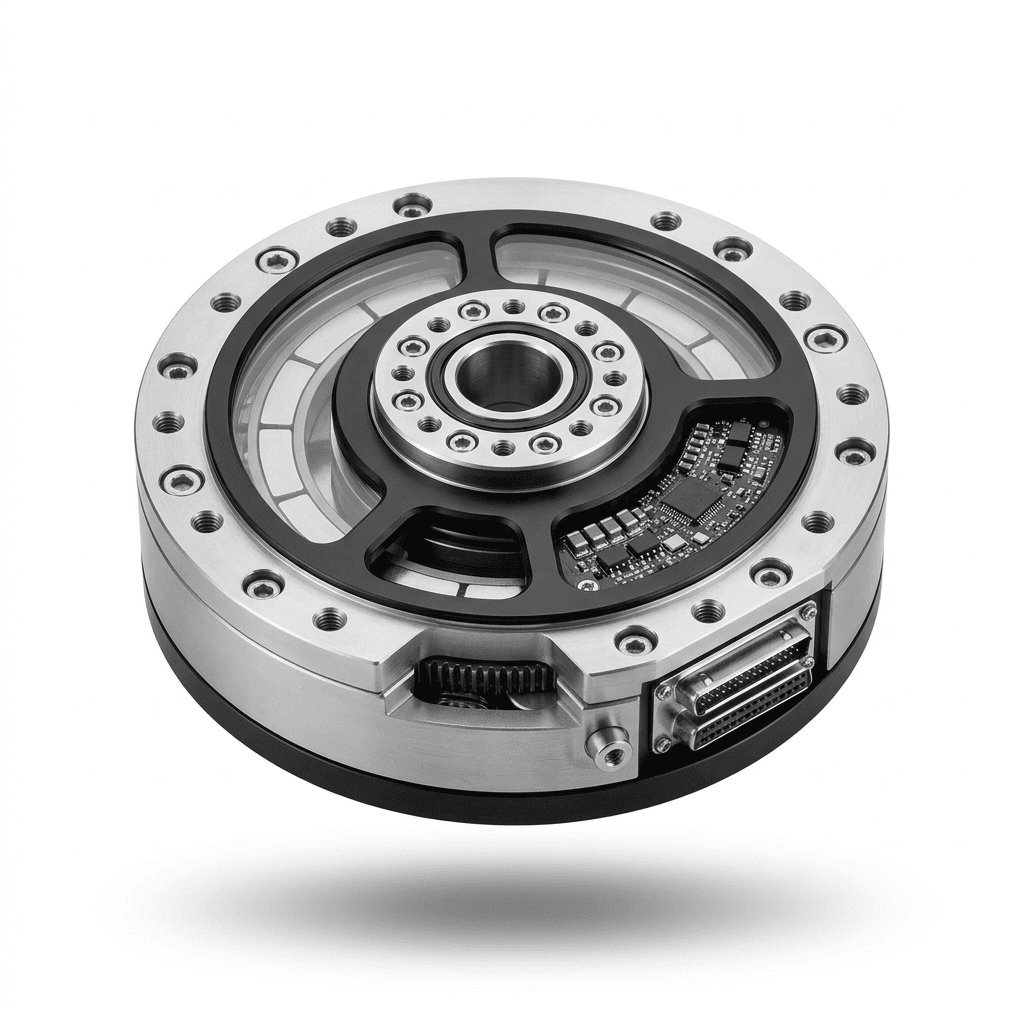
Published and reviewed: October 30, 2026. Scope: Global OEM sourcing, English-language engineering guidance. This is a literature-based comparison with reproducible, hypothetical calculations and a supplier validation worksheet. It contains no comparative production test dataset. Ratio ranges are examples, not standardized architecture boundaries; QDD here means a torque-dense motor with low reduction, illustrated at 4:1–10:1. Product images illustrate packaging, not measured performance. Application approval requires model-specific tests and the standards applicable in the destination market.
If your engineering group is preparing a Bill of Materials (BOM) for prototype builds or pilot volume, evaluate our modular robotic joint actuator portfolio or submit your target duty cycle to our engineering team for an RFQ review.
1. Executive Summary & Sourcing Trade-Off Matrix
Comparing catalog torque-to-weight ratios alone can hide the trade-off between reflected inertia, motor heating, and transmission limits. A higher ratio multiplies motor torque but also increases the rotor inertia reflected to the output. A lower ratio can improve backdrivability but may require more motor current for a given output torque. Actual shock survival and steady-state temperature depend on the complete design.
The table below outlines the core trade-offs between Quasi-Direct Drive and High-Ratio Geared joint modules across key engineering, control, and procurement dimensions:
| Architectural Metric | Quasi-Direct Drive (QDD) Module | High-Ratio Geared Module (Harmonic / Cycloidal) | Procurement & Specification Impact |
|---|---|---|---|
| Transmission Type & Ratio (N) | Low-ratio planetary or spur stage; examples: 4:1–10:1 | Examples: strain-wave 50:1–160:1; cycloidal 30:1–100:1 | Obtain the actual ratio and torque-speed envelope; topology alone does not fix the ratio. |
| Reflected Rotor Inertia (N² × Jm) | Rotor multiplier 16–100 for the example ratios | Rotor multiplier 900–25,600 across the example ratios | Compare actual rotor inertia and output-referred transmission inertia, not ratio alone. |
| Mechanical Backdrivability | Often lower breakaway resistance | Friction and hysteresis can make backdriving harder | Measure at specified temperature, speed, brake state, and motor terminal condition. |
| Impact Shock Tolerance | Low reflected inertia can help the joint yield | Transmission overload ratings and structural compliance matter | Require a torque-time shock profile and test evidence; neither architecture has a universal impact rating. |
| Torque Sensing & Proprioception | Current-based estimation can support force control | Precision output feedback may justify a torque sensor or calibrated dual encoders | Compare measured estimation error and bandwidth; sensor savings require a model-specific quote. |
| Continuous Holding Heat (Copper Loss) | Low ratio may require higher motor current | Higher ratio may reduce required motor torque | Compare motor constants, winding resistance, cooling, and holding tests; a brake changes the operating mode. |
| Kinematic Backlash & Lost Motion | Depends on gear clearance and assembly | Low nominal backlash is possible, with load-dependent elastic deflection | Specify backlash, hysteresis, stiffness, and transmission error separately. |
| Actuator Form Factor (Envelope) | Often a wide, short motor package | May permit a smaller motor diameter; reducer packaging varies | Compare complete CAD envelopes, bearings, brakes, and cable exits. |
| BOM Cost & Service Life | Simple reduction may reduce gearbox cost; motor and inverter may cost more | Precision reducer cost and maintenance depend on the selected model | Obtain comparable quotes, load spectra, lubrication conditions, and documented life calculations. |
| Primary Target Applications | Quadruped hips/knees, humanoid lower limbs, bionic exoskeletons, haptic interfaces | Cobot wrists/shoulders, industrial SCARA/6-DOF arms, humanoid waist roll/yaw, heavy mobile lifters | System architects should mix architectures based on joint dynamics rather than forcing a single topology across all axes. |
2. Mechanical & Dynamic Fundamentals: Reflected Inertia and Impact Transparency
The foundational physical principle governing the distinction between QDD and high-ratio joint modules is reflected rotor inertia. When an external force acts upon a robotic joint output (such as an unexpected obstacle collision or a dynamic foot strike on hard concrete), the motor rotor must accelerate in reverse for the joint to yield passively.
For a rigid transmission, the motor and transmission inertia referred to the output can be approximated as:
Jref = N² × Jm + Jgear,outWhere:
Nis motor speed divided by output speed.Jmis rotor moment of inertia in kg·m².Jgear,outis transmission inertia already referred to the output. Link and payload inertia must be added separately in the robot model.
The N² Penalty in High-Ratio Actuation
To isolate the ratio effect, assume two hypothetical modules have the same rotor inertia, Jm = 0.85 × 10⁻⁴ kg·m², and neglect transmission inertia:
-
QDD example, N = 6:
Jref = 36 × 0.85 × 10⁻⁴ = 0.00306 kg·m². -
High-ratio example, N = 100:
Jref = 10,000 × 0.85 × 10⁻⁴ = 0.85 kg·m².
The rotor contribution is about 278 times higher in this controlled comparison. Real QDD motors may have a larger rotor inertia than high-speed motors; use both suppliers' actual values before drawing a product-level conclusion.
Conceptual Comparison: Backdrivability and Impact Load Paths
Conceptual illustration, not a shock test result. Low output-referred inertia can improve backdrivability. Regeneration depends on speed, inverter state, and DC bus absorption capacity; a torque sensor measures load but does not absorb impact energy. Both architectures require transmission, bearing, and system-level validation.
Physical Impact Mitigation on Robot Limbs
Contact duration depends on foot compliance, terrain, speed, and control. Wensing et al. (2017) introduce an impact mitigation factor and demonstrate backdrivable proprioceptive actuation on the MIT Cheetah. This supports an architecture trade-off, not a universal shock-survival limit.
A separate, simplified undamped mass-spring impact model gives:
Fpeak ≈ vimpact × √(kcontact × Meffective)Here Meffective is the effective translational mass at contact, including joint inertias mapped through the robot geometry. The model assumes a linear contact spring and omits damping and active control; it cannot predict tooth stress or certify drop survival. Backdrivability is the ability to yield through motion, distinct from the elastic compliance of a spring.
3. Torque Density vs. Thermal Limits: Copper Loss (I²R)
Procurement teams must compare thermal dissipation under static and continuous loads alongside dynamic response. Define continuous torque density as continuous output torque divided by complete module mass (N·m/kg), including driver, bearings, encoders, and any brake. Compare at the same ambient temperature, mounting, cooling, output speed, and winding temperature limit. State peak torque density separately with its pulse duration and recovery time.
Sizing and the Copper Loss Dilemma
For a simplified non-salient motor model, use a torque constant Kt defined against peak q-axis current Iq, with zero d-axis current:
τm = Kt × Iq
τout ≈ N × η × Kt × Iq
Pcopper = 1.5 × Iq² × Rphase
        ≈ 1.5 × [τout / (N × η × Kt)]² × Rphase
Rphase is phase-to-neutral winding resistance at the stated temperature. Suppliers may specify RMS phase current, line-to-line resistance, or another torque-constant convention; convert these before calculating. The 1/N² relationship holds only with motor constants, resistance, and efficiency fixed. The efficiency η is a lumped moving-load approximation; at zero speed, use measured holding current and friction rather than a catalog running efficiency.
The following deliberately hypothetical inputs illustrate sensitivity to ratio and motor sizing. They are not matched commercial actuators or validated continuous ratings:
Hypothetical 60 N·m output load (moving-load η approximation):

Scenario A: QDD Actuator (N = 6, η = 0.95, Kt = 0.15 N·m/A, R = 0.18 Ω)
  Motor torque required: τm = 60 / (6 × 0.95) ≈ 10.53 N·m
  Phase current Iq = 10.53 / 0.15 = 70.2 A
  Stator Copper Loss Ploss = 1.5 × (70.2)² × 0.18 ≈ 1,330 W

Scenario B: Harmonic Module (N = 100, η = 0.75, Kt = 0.05 N·m/A, R = 0.35 Ω)
  Motor torque required: τm = 60 / (100 × 0.75) = 0.80 N·m
  Phase current Iq = 0.80 / 0.05 = 16.0 A
  Stator Copper Loss Ploss = 1.5 × (16.0)² × 0.35 ≈ 134 W
The assumed QDD case produces about 9.9 times the copper loss of the assumed high-ratio case. Both values may exceed a compact module's thermal capacity; neither establishes a safe holding rating. Gear, iron, and inverter losses are omitted. Confirm temperature rise on the proposed mounting and cooling system.

Duty Cycle and Holding Tests
-
Continuous loading and static holding:
- Request stabilized winding and case temperatures at the required torque, speed, ambient, and mounting conditions. Zero-speed holding needs its own test point.
- Check winding, magnet, bearing, and electronics limits separately. Neither ratio nor insulation class establishes a universal throttling time or allowable case temperature.
-
Intermittent and locomotion cycles:
- Send the full torque-speed-time trace, including stance, swing, acceleration, deceleration, dwell, and rest. A gait with frequent acceleration or electrical braking cannot automatically be classified as simple intermittent duty.
- Use cycle RMS current to estimate average copper loss, then validate transient winding temperature, peak current duration, and bus energy. Ask the supplier to identify the applicable duty classification and standard edition.
4. Torque Sensing & Proprioception: Motor Current vs. External Sensors
An output torque sensor adds hardware, calibration, wiring, and packaging requirements. Compare these costs with the accuracy and diagnostic coverage required by the application; there is no universal sensor cost or size saving for QDD.
The Proprioceptive Advantage of QDD
Lower transmission friction can make current-based output torque estimation more practical. A simplified estimator is:
τestimated ≈ N × Kt × Iq − τfriction − Jref × αoutThe friction and inertia terms are output-referred; this model neglects transmission elasticity and other losses. Calibration must cover acceleration, direction reversal, temperature, and load. Katz's MIT thesis documents a low-cost modular actuator for dynamic robots; its results are specific to the hardware and experiments described.
Current sampling frequency, current-loop update rate, closed-loop torque bandwidth, and contact detection latency are different quantities. Request measured response and estimation error rather than treating a 1 kHz command rate as 1 kHz force bandwidth.
When High-Ratio Drives Benefit from Output Feedback
High-ratio transmissions may introduce temperature-dependent friction, stiction, hysteresis, and torsional deflection. A calibrated model, output torque sensor, or dual encoders can improve load estimation. Dual encoders require a validated stiffness model and sufficient resolution; none of these options automatically provides a safety function.
ISO/TS 15066:2016 addresses collaborative industrial robot systems and their work environment alongside ISO 10218 requirements. It does not prescribe one sensor arrangement for every high-ratio joint. Select sensing and diagnostics through the application risk assessment and validate the complete robot system.
5. Architectural Decision Framework: Sizing by Robotic Joint Function
Select the architecture per axis using the load spectrum, package, and control requirements. The following tree is a screening aid: each branch still requires torque-speed, thermal, stiffness, and impact validation.
                         [ROBOT ACTUATION SELECTION TREE]
                                        |
                 Is the joint subjected to repeated ground impacts
                 or sudden environmental collisions (e.g. foot/wheel)?
                                   /         \
                             YES  /           \  NO
                                 /             \
                  [SHORTLIST: QDD]             Does the joint require high
                  - Ratio N = 5:1 to 9:1        continuous holding torque (S1)
                  - High backdrivability        in a tight outer diameter?
                  - Proprioceptive force                     /         \
                  - Examples: Quadruped Hip,           YES  /           \  NO
                    Knee; Biped Ankle roll                 /             \
                                              [SHORTLIST: HIGH-RATIO] Is low lost motion
                                              - Harmonic/Cycloidal    under load
                                              - Ratio N = 50:1-120:1  essential without
                                              - Integrated brake      external compliance?
                                              - Examples: Waist Yaw,       /         \
                                                Shoulder Pitch,      YES  /           \  NO
                                                Cobot Base Axis          /             \
                                                                        /               \
                                                        [HIGH-RATIO HARMONIC]    [HYBRID / QDD]
                                                        - Dual encoder           - Medium ratio
                                                        - Verify lost motion       (15:1 - 25:1)
Application Breakdown Across Robot Morphologies
-
Dynamic quadrupeds:
- Hip and knee: low-ratio QDD is a candidate where impact response and fast leg repositioning dominate. Confirm actual output inertia and repeated-impact capability; this is not a claim about every commercial quadruped.
-
Bipedal humanoids:
- Ankle and knee: compare rotary QDD, higher-ratio rotary drives, and linear mechanisms against the actual torque-speed trace and linkage geometry.
- Hip and waist: evaluate continuous support torque, bearing moments, and postural stiffness alongside transient loads. Axis names alone do not determine the best ratio.
- Shoulder, elbow, and wrist: compare package diameter, carried mass, continuous payload, lost motion, and force-control requirements. QDD remains an option where its motor envelope fits.
-
Collaborative arms and mobile manipulators:
- Base, shoulder, and elbow: high-ratio drives are candidates for payload support in tight packages. Specify holding brake behavior and the required sensing architecture separately.
- Wrist: prioritize complete tool payload, cable routing, and stiffness. End-effector accuracy and repeatability depend on the full robot geometry, calibration, and control, not reducer backlash alone.
6. Manufacturing & Quality Engineering Checkpoints for OEM Sourcing
Use these checkpoints to request evidence for the proposed design. They are procurement questions, not universal manufacturing requirements.
QDD Planetary Gearbox Engineering
-
Gear Material & Heat Treatment:
- Request material certificates, heat-treatment process, case depth where applicable, surface hardness, and core properties against the approved drawing.
- Have the supplier justify material and process choices with gear stress and fatigue calculations for the load spectrum. Different alloys and manufacturing routes are not interchangeable by name alone.
- Specify gear accuracy and inspection method separately from assembled backlash, noise, and efficiency. Gear precision does not eliminate electromagnetic cogging.
-
Planet Carrier and Bearing Rigidity:
- Request carrier deflection analysis, bearing load ratings, preload or clearance specifications, and lubrication requirements.
- Check reversing torque and radial/axial load cases against the proposed bearing arrangement and assembly process.
-
Motor Electromagnetic Design:
- Compare motor diameter, stack length, rotor inertia, thermal path, and cogging torque rather than choosing by pole count alone.
- Request torque constant and winding resistance with their current and temperature conventions. Use these together with measured thermal resistance to compare continuous torque capability.
Embedded Driver & Inverter Electronics
-
Current Sampling Architecture:
- Request current-sensor topology, ADC resolution in bits, sampling rate in samples/second, offset drift, and calibration method.
- Specify PWM frequency and current-loop update rate separately from measured control bandwidth, torque ripple, and communication cycle time.
-
Regenerative Energy Dissipation (Braking Chopper):
- Either architecture can regenerate during suitable operating conditions. Request peak regenerative power and energy for the specified motion profile.
- Confirm a compatible battery, regenerative supply, or correctly rated brake chopper and resistor can absorb that energy. A transient TVS clamp alone is not a repetitive braking-energy sink; verify bus voltage and component limits in testing.
7. Sourcing & RFQ Checklist (Buyer Validation Worksheet)
Copy this worksheet into your RFQ. Set numerical acceptance limits from your robot model before supplier approval; no fixed ratio, peak multiplier, or breakaway threshold is suitable for every joint.
| Inspection Gate | Required Supplier Technical Deliverable | Pass / Fail Acceptance Criteria | Sourcing Risk Addressed |
|---|---|---|---|
| 1. Reflected Inertia & Ratio | Rotor inertia, ratio, and output-referred transmission inertia, with calculation assumptions. | Values fit the robot simulation's inertia budget and declared uncertainty; resolve missing values before approval. | Avoids unexpected inertia and control mismatch. |
| 2. Continuous vs. Peak Torque | Torque-speed curves, complete module mass, thermal test setup, peak duration, and recovery time. | Target cycle stays within winding, drive, and transmission limits at the specified ambient and mounting. | Exposes peak-only catalog ratings and incomplete torque-density comparisons. |
| 3. Backdrive Breakaway Torque | Breakaway and running torque at agreed temperature, direction, speed, brake state, and terminal condition. | Results meet the application-specific passive resistance budget across the test conditions. | Checks manual guidance and current-based estimation assumptions. |
| 4. Impact Shock Rating | Allowable torque-time profile, radial/axial loads, cycle count, and a representative physical test report. | No unacceptable deformation, lost-motion change, bearing damage, or functional failure under the agreed load spectrum. | Checks repeatable impact capability rather than an unqualified g-rating. |
| 5. Thermal Sensor Integration | Sensor type and location, calibration, telemetry mapping, and derating/fault behavior. | Winding temperature is measured or estimated with validated error and trip margins; a PCB sensor alone is not a winding measurement. | Reduces undetected local overheating. |
| 6. Backlash & Transmission Error | Torque-angle hysteresis loop and transmission error at agreed load, temperature, and fixture stiffness. | Backlash, stiffness, hysteresis, and error meet separate joint budgets; validate robot pose performance separately. | Avoids confusing reducer lost motion with end-effector repeatability. |
| 7. Regeneration & Brake Chopper | Bus voltage limits, peak and repetitive energy capacity, resistor duty, and supply absorption limits. | The worst agreed deceleration profile stays within bus and thermal limits, including simultaneous regeneration by multiple joints. | Controls bus overvoltage and braking-energy overload. |
Before requesting a quote, confirm:
- Torque-speed-time trace, payload, and emergency-stop loads are attached.
- Continuous and peak torque density use the same complete-module mass boundary.
- Ambient temperature, mounting, cooling, and required operating life are defined.
- Breakaway, lost-motion, and shock acceptance limits have a named engineering owner.
- Interface drawing revision, voltage, fieldbus cycle, quantities, destination, and delivery window are included.
Share the completed worksheet with our engineering team for a model-specific sourcing review. Mark unknown limits as open questions rather than accepting a generic catalog claim.
8. Frequently Asked Questions (FAQ)
Can a QDD joint module hold a robotic arm horizontally without overheating?
A QDD can hold continuously if the required holding current and thermal path keep it within its validated continuous rating. Check zero-speed winding temperature on the proposed mount. A suitably rated holding brake or gravity counterbalance can reduce energized holding demand; confirm brake load, engagement sequence, and fault behavior separately.
How do I accurately measure backdrivability in a supplier's sample module?
Secure the module on a bench, isolate stored energy, and release any brake using the supplier's procedure. With motor power disconnected and phase leads open-circuit, use a calibrated torque transducer or lever arm and force gauge. Increase torque slowly to record breakaway, then measure running resistance at an agreed low speed, for example 1 rpm. Test both directions and record temperature and terminal state. Compare with the joint's resistance budget; shorted motor terminals give a different result.
Why not use a direct-drive (DD) motor with no gearbox at all (N = 1:1)?
Direct drive removes gear backlash and gear friction, but bearings, cogging, rotor inertia, and control still affect transparency. Producing the full output torque without reduction can increase motor diameter, mass, or cooling demand. Compare actual continuous torque, total mass, and thermal conditions; there is no universal motor weight for a given torque. QDD is one compromise, not an optimum for every axis.
Can QDD replace cobot harmonic drives for ISO/TS 15066 safety compliance?
It may be an architecture candidate, but replacing the joint does not establish compliance. ISO/TS 15066:2016 applies to collaborative industrial robot systems and their environment. Validate transient and quasi-static contact, trapping hazards, stopping behavior, payload and tool effects, and safety functions for the complete application. Lower reflected inertia can help impact response; ordinary current sensing is not automatically a safety-rated contact detector.
What causes cogging torque in QDD actuators, and how is it mitigated?
Cogging comes from the interaction of rotor magnets and stator slot geometry, even without current. Gear reduction transforms motor torque disturbances and transmission friction may mask their feel. Motor geometry, skew, winding design, and calibrated compensation can reduce the effect, with design trade-offs. Request unpowered cogging and powered torque-ripple measurements separately.
What fieldbus protocol is recommended for QDD actuators?
Compare EtherCAT, CANopen, or CAN-FD against axis count, payload size, synchronization, jitter, and fault-recovery needs. For a proposed 1 kHz command cycle, require an end-to-end timing budget and measurements under full bus load. Verify the selected drive's supported modes and protocol profile; protocol name or bit rate alone does not establish torque-control bandwidth.
9. Sources, Evidence Boundaries & Standards
- Wensing, P. M., Wang, A., Seok, S., Otten, D., Lang, J., & Kim, S. (2017). Proprioceptive Actuator Design in the MIT Cheetah: Impact Mitigation and High-Bandwidth Physical Interaction for Dynamic Legged Robots. IEEE Transactions on Robotics, 33(3), 509–522. Published paper, DOI: 10.1109/TRO.2016.2640183. Supports the backdrivability and impact-mitigation framework; it does not certify generic QDD modules.
- International Organization for Standardization (ISO). ISO/TS 15066:2016 Robots and robotic devices — Collaborative robots. Official scope and publication record. Supports the industrial collaborative-system scope. The public abstract is not the full specification or evidence of product compliance; confirm applicable editions and local requirements for the destination market.
- Katz, B. G. (2018). A low cost modular actuator for dynamic robots. S.M. thesis, Department of Mechanical Engineering, Massachusetts Institute of Technology. MIT DSpace thesis record. Documents a specific modular actuator and dynamic robot implementation, not universal torque density, lifetime, or supplier pricing.
The calculations in Sections 2–3 use stated hypothetical inputs. The RFQ criteria are an editorial validation framework, not measured supplier results or mandated thresholds. Recheck this guide when a selected model, application load spectrum, or applicable standard changes.
10. Engineering Support & RFQ Sourcing
For a QDD, strain-wave, or planetary module sourcing review, send your requirements and ask our engineering team to confirm model-specific availability and validation deliverables:
- Target ratio, torque-speed trace, and motor envelope
- Encoder arrangement and holding brake requirements
- Voltage, fieldbus, command cycle, and fault behavior
- Prototype quantities and required dynamometer, thermal, and impact test reports
Contact our engineering department directly with your joint packaging constraints, payload curves, and target delivery schedule:
- Engineering Inquiries: [email protected]
- Product Catalog: Browse Robotic Joint Module Product Lines
- Direct Sourcing Review: Request an Engineering & RFQ Consultation
Author

More Posts
48V vs 24V Robotic Joint Modules: Power Density and Sourcing Guide
Compare 48V vs 24V robotic joint modules for power density, thermal limits, safety scope, RFQ checks, and sourcing decisions before supplier review starts.

Crossed Roller vs Four-Point Contact Bearings in Hollow-Shaft Robotic Joint Modules: Tilting Moment Rigidity, Runout Tolerances, Preload, and Sourcing Guide
Compare crossed roller vs four-point contact bearings for robot joints. Evaluate tilting stiffness, runout, preload and thermal fits, then prepare your RFQ.
Series Elastic Actuators (SEA) vs Quasi-Direct Drive (QDD) Joint Modules: Force Bandwidth, Energy Recovery, and Humanoid Sourcing Guide
Compare SEA vs QDD robotic joint modules for force bandwidth, energy recovery, holding heat, and OEM sourcing. Use the checklist to prepare your actuator RFQ.